Wireless Mobile Battery Charger Circuit Project Report
In this project the method is divided into two major activities which is to purpose circuit construction and to. The project is a device to transfer power wirelessly instead of using conventional copper cables and current carrying wires and also measure battery charge.
![]()
Wireless Mobile Charger Circuit Diagram Engineering Projects
This is done using charging a resonant coil from AC and then transmitting subsequent power to the resistive load.
Wireless mobile battery charger circuit project report. Through research and design this prototype will critically address and analyze the major design challenges that bring about longer charging periods of the new inductive wireless charging compared to the. Inductance is the property of the conductor in which the current flowing in a. And then the rectifier circuit in the receiver will convert the RF microwave signal into DC signal.
Wireless Mobile Charging is one of the trending topic in the field of electronics thus we also decided to build a Wireless Mobile Charger Circuit Diagram using various commonly available components. The goal of this project Wireless power transmission mobile charger circuit using inductive coupling is to charge a low power device using wireless power transmission. Wireless Mobile Charger Circuit Design.
A Project Report On MOBILE CHARGER USING PIEZOELECTRIC EFFECT Submitted By NAVED AHMED KHAN ZUBER MOHAMMAD QAASIM SHAIKH ABDUL WAFEE Under the guidance of PROF. Nowadays mobile phones have become an integral part of everyones life and hence require frequent charging of battery owing to longer duration usage. Tech Gajrula UP.
Semester VIII ELECTRONICS TELECOMMUNICATION DEPARTMENT 2013 - 2014 from Rizvi College of. WIRELESS POWER TRANSFER. In our Wireless battery charger we use two circuits.
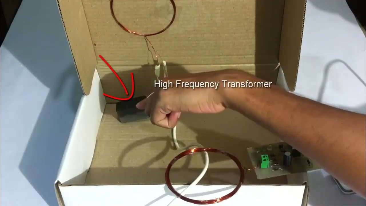
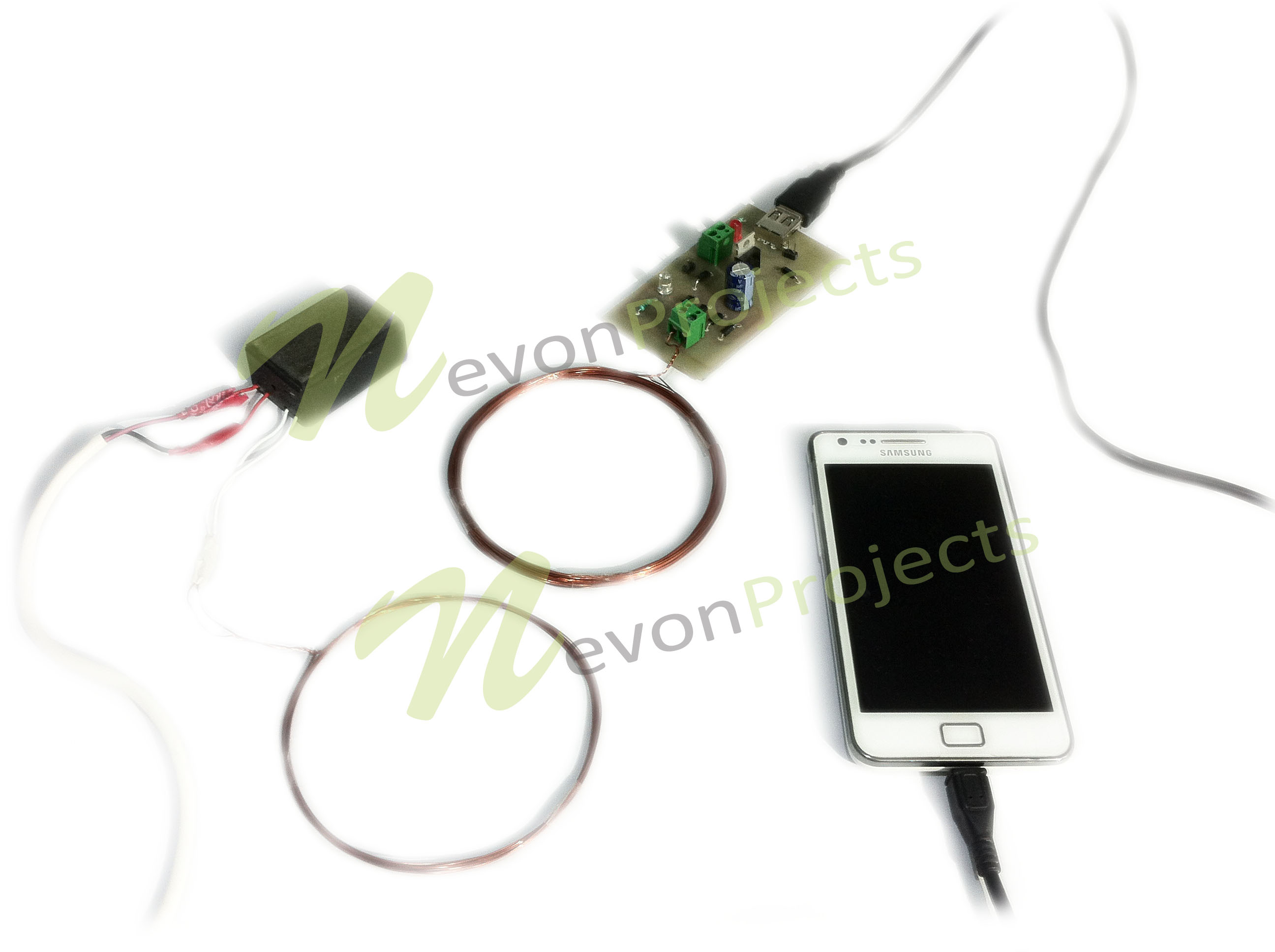
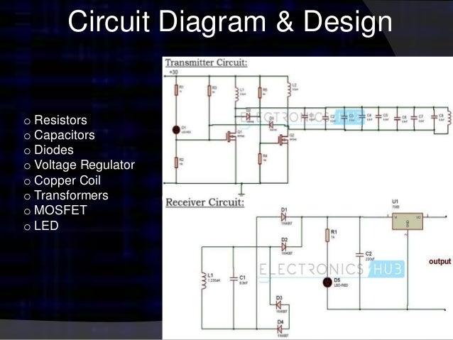
JUNAID MANDVIWALA Submitted as a partial fulfillment of Bachelor of Engineering BE. This wireless battery charger is designed to operate at 900 MHz. These circuits require only resistors capacitors diodes Voltage regulator copper coils and Transformer.
Wireless Mobile Charger Circuit Design. We demonstrate the system using a charging pad where user just needs to place his adapter circuit to charge the mobile phone. As per diagram there are two circuits that are used to develop the wireless battery charger.
This circuit may be used as wireless power transfer circuit wireless mobile charger circuit wireless battery charger circuit etc. Here is the block diagram of the overall design. The advantage of this.
It will transmit power to the receiver side. In this project a power transmitter acts as the power source. Hence in this work a wireless battery charger has been proposed for mobile phone charging which is expected to eliminate all the hassles with todays battery technology.
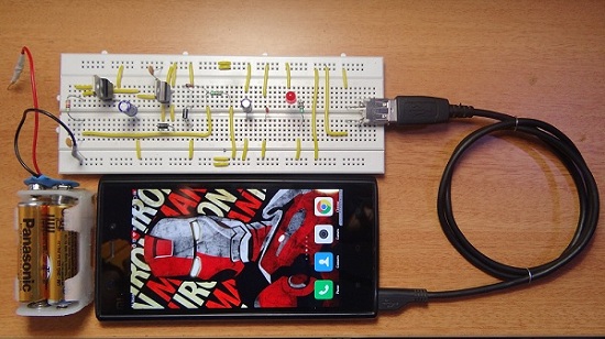
Battery Oscillator Circuit 1. This project explains a simple wireless battery charger circuit that charges your mobile when placed near the transmitter. This is done using charging a resonant coil from AC and then transmitting subsequent power to the resistive load.
Power is transferred from transmitter to the receiver wirelessly based on the principle of inductive coupling. These circuits require only resistors capacitors diodes Voltage regulator copper coils and Transformer. The project Wireless Mobile Charger Circuit Diagram posted here can deliver 271mA at 52V so you charge mobile phone and also can be used to drive low power load such as LED 1 and.
Then the transmit-ter coil transmits coupling magnetic field by. Wireless battery charger circuit design is very simple and easy. This circuit may be used as wireless power transfer circuit wireless mobile charger circuit wireless battery charger circuit etc.
The power is transferred using inductive coupling resonant induction or electromagnetic wave transmission depending on whether its short range mid-range or high rangeThe goal of this project Wireless power transmission mobile charger circuit using. The system allows user to wirelessly charge his mobile phone without plugging in the mobile adapter. This Wireless Mobile Battery Charger project is using technique of inductive coupling.
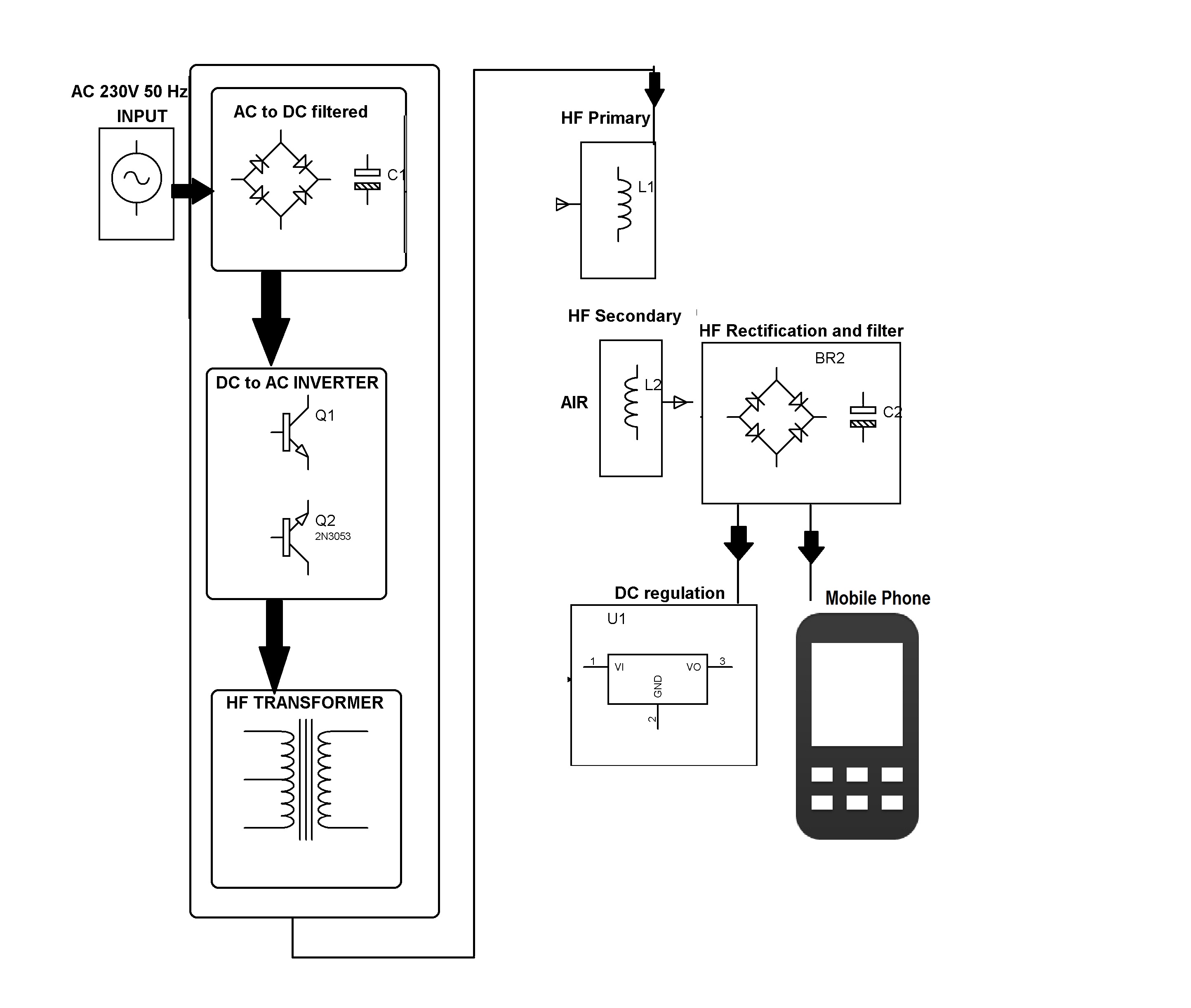
After the DC signal is produced the charging circuit will store the power into the battery. The concept of wireless power transfer was introduced by Nikolas Tesla. In our Wireless battery charger we use two circuits.
This circuit has oscillator circuit transmitter coil and DC power source. The first one is the transmitter circuit and is used to generate voltage on wireless fashion. The basic concept of his technique was applied in transformer construction.
1Block diagram of wireless power transfer system In this project supply voltage 12 DC drives oscillator circuit as push-pull driver to operate transmitter coil. This system demonstrates the concept of wireless mobile charging system. 67 MHz Transmitter Coil Receiver Coil DC Level Stabilizer Charging Battery Fig.
For this purpose we. With this technique the power from AC or DC can be transfer through the medium of magnetic field or air space. The oscillator circuit has two n channel MOSFETS 4148 diodes and IRF 540.
Wireless battery charger circuit design is very simple and easy. Wireless power transmission is effective in areas where wire system is unreachable or impossible. Low power wirelessly to charge low power device like mobile.
Wireless Mobile Charging Project. This circuit mainly works on the principle of mutual inductance. The goal of this project is to design a prototype wireless energy charger for low power devices with specific emphasis on mobile phones.
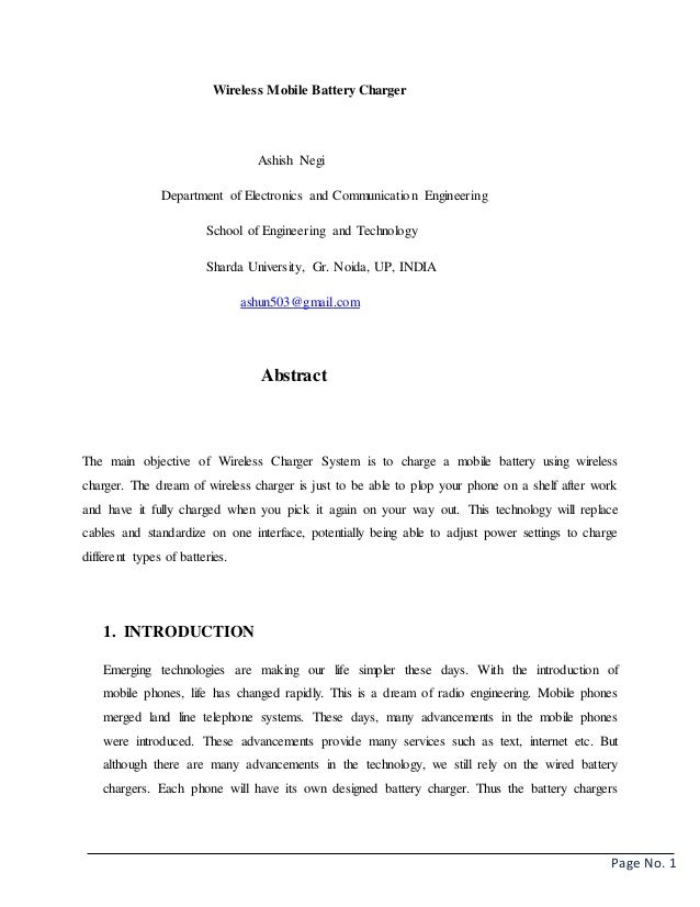
India Abstract - The main objective of Wireless Charger System is to charge the mobile battery by using wireless charger. Mobile Cellphone Battery Charging Circuit with Explanation A mobile battery charger circuit is a device that can automatically recharge a mobile phones battery when the power in it gets low. Enhancement of Wireless Power Transfer.
The project is meant. The technology will replace cables and standardize on one interface potentially being able to charge 1000mAh battery. It also charges the battery using wireless power transfer concept till it reaches 100 capacity.
Advanced Wireless Mobile Charging Project
Advanced Wireless Mobile Charging Project
![]()
Wireless Power Transmission Mobile Charger Circuit Using Inductive Coupling Wireless Projects Mepits

Wireless Power Transmission Mobile Charger Circuit Using Inductive Coupling Wireless Projects Mepits
![]()
Wireless Mobile Charger Circuit Diagram Engineering Projects

Wireless Power Transmission Mobile Charger Circuit Using Inductive Coupling Wireless Projects Mepits

Wireless Mobile Charging Engineering Projects
How To Make Portable Battery Charger
Wireless Mobile Charger Circuit Diagram Engineering Projects
Wireless Mobile Charger
Smart Wireless Battery Charging With Charge Monitor Project
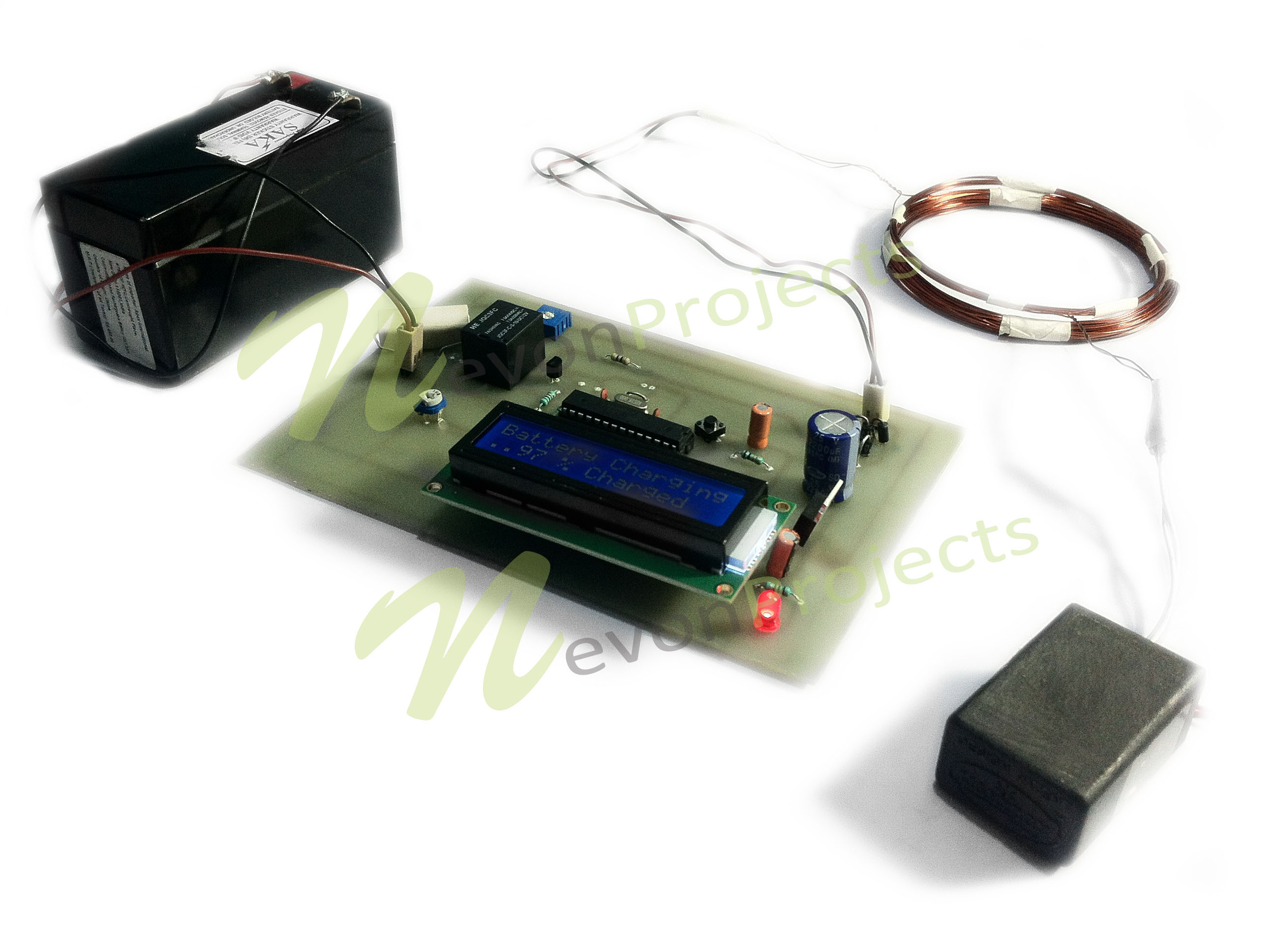
Wireless Mobile Battery Charger
Advanced Wireless Mobile Charging Project

17 Simulation Of Wireless Mobile Charger Circuit Diagram 17 Download Scientific Diagram
![]()
Wireless Mobile Charger Circuit Diagram Engineering Projects

Wireless Mobile Battery Charger

Wireless Mobile Charger Circuit Diagram Engineering Projects
Pdf A Working Model For Mobile Charging Using Wireless Power Transmission

Pdf Wireless Mobile Charger Md Amin Azad 1521233642 Academia Edu
Post a Comment for "Wireless Mobile Battery Charger Circuit Project Report"